Friday, July 29, 2022

Types of Network Topology

Types of Network Topology


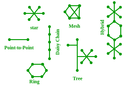
The arrangement of a network that comprises nodes and connecting lines via sender and receiver is referred to as network topology. The various network topologies are:

Mesh Topology:

In a mesh topology, every device is connected to another device via a particular channel. In Mesh Topology, the protocols used are AHCP (Ad Hoc Configuration Protocols), DHCP (Dynamic Host Configuration Protocol), etc.


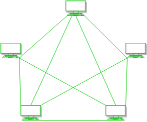
Figure 1: Every device is connected with another via dedicated channels. These channels are known as links. 
 

  • Suppose, the N number of devices are connected with each other in a mesh topology, the total number of ports that are required by each device is N-1. In Figure 1, there are 5 devices connected to each other, hence the total number of ports required by each device is 4. Total number of ports required=N*(N-1).
  • Suppose, N number of devices are connected with each other in a mesh topology, then the total number of dedicated links required to connect them is NC2 i.e. N(N-1)/2. In Figure 1, there are 5 devices connected to each other, hence the total number of links required is 5*4/2 = 10.

Advantages of this topology: 

  • It is robust.
  • The fault is diagnosed easily. Data is reliable because data is transferred among the devices through dedicated channels or links.
  • Provides security and privacy.

Problems with this topology: 

  • Installation and configuration are difficult.
  • The cost of cables is high as bulk wiring is required, hence suitable for less number of devices.
  • The cost of maintenance is high.

Star Topology:

In star topology, all the devices are connected to a single hub through a cable. This hub is the central node and all other nodes are connected to the central node. The hub can be passive in nature i.e., not an intelligent hub such as broadcasting devices, at the same time the hub can be intelligent known as an active hub. Active hubs have repeaters in them. In Star Topology, many popular Ethernet LAN protocols are used as CD(Collision Detection), CSMA (Carrier Sense Multiple Access), etc.


Figure 2: A star topology having four systems connected to a single point of connection i.e. hub. 

Advantages of this topology: 

  • If N devices are connected to each other in a star topology, then the number of cables required to connect them is N. So, it is easy to set up.
  • Each device requires only 1 port i.e. to connect to the hub, therefore the total number of ports required is N.
  • It is Robust. If one link fails only that link will affect and not other than that.
  • Easy to fault identification and fault isolation.

Problems with this topology: 

  • If the concentrator (hub) on which the whole topology relies fails, the whole system will crash down.
  • The cost of installation is high.
  • Performance is based on the single concentrator i.e. hub.

Bus Topology:

Bus topology is a network type in which every computer and network device is connected to a single cable. It transmits the data from one end to another in a single direction. No bi-directional feature is in bus topology. It is a multi-point connection and a non-robust topology because if the backbone fails the topology crashes. In Bus Topology, various MAC (Media Access Control) protocols are followed by LAN ethernet connections like TDMA, Pure Aloha, CDMA, Slotted Aloha, etc.


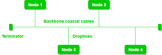
Figure 3: A bus topology with shared backbone cable. The nodes are connected to the channel via drop lines. 

Advantages of this topology: 

  • If N devices are connected to each other in a bus topology, then the number of cables required to connect them is 1, which is known as backbone cable, and N drop lines are required.
  • The cost of the cable is less compared to other topologies, but it is used to build small networks.

 Problems with this topology: 

  • If the common cable fails, then the whole system will crash down.
  • If the network traffic is heavy, it increases collisions in the network. To avoid this, various protocols are used in the MAC layer known as Pure Aloha, Slotted Aloha, CSMA/CD, etc.
  • Security is very low.
     

Ring Topology:

In this topology, it forms a ring connecting devices with exactly two neighboring devices.

A number of repeaters are used for Ring topology with a large number of nodes, because if someone wants to send some data to the last node in the ring topology with 100 nodes, then the data will have to pass through 99 nodes to reach the 100th node. Hence to prevent data loss repeaters are used in the network.

The transmission is unidirectional, but it can be made bidirectional by having 2 connections between each Network Node, it is called Dual Ring Topology. In-Ring Topology, the Token Ring Passing protocol is used by the workstations to transmit the data.


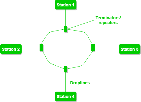
Figure 4: A ring topology comprises 4 stations connected with each forming a ring. 

The following operations take place in ring topology are : 
 

  1. One station is known as a monitor station which takes all the responsibility to perform the operations.
  2. To transmit the data, the station has to hold the token. After the transmission is done, the token is to be released for other stations to use.
  3. When no station is transmitting the data, then the token will circulate in the ring.
  4. There are two types of token release techniques: Early token release releases the token just after transmitting the data and Delay token release releases the token after the acknowledgment is received from the receiver.

Advantages of this topology: 

  • The possibility of collision is minimum in this type of topology.
  • Cheap to install and expand.

Problems with this topology: 

  • Troubleshooting is difficult in this topology.
  • The addition of stations in between or removal of stations can disturb the whole topology.
  • Less secure. 

Tree Topology :

This topology is the variation of the Star topology. This topology has a hierarchical flow of data. In Tree Topology, SAC (Standard Automatic Configuration ) protocols like DHCP and SAC are used.


Figure 5: In this, the various secondary hubs are connected to the central hub which contains the repeater. This data flow from top to bottom i.e. from the central hub to the secondary and then to the devices or from bottom to top i.e. devices to the secondary hub and then to the central hub. It is a multi-point connection and a non-robust topology because if the backbone fails the topology crashes.
 

Advantages of this topology : 

  • It allows more devices to be attached to a single central hub thus it decreases the distance that is traveled by the signal to come to the devices.
  • It allows the network to get isolated and also prioritize from different computers.

Problems with this topology :  

  • If the central hub gets fails the entire system fails.
  • The cost is high because of cabling.

Hybrid Topology :

This topology technology is the combination of all the various types of topologies we have studied above. It is used when the nodes are free to take any form. It means these can be individuals such as Ring or Star topology or can be a combination of various types of topologies seen above. Each individual topology uses the protocol that has been discussed earlier.

Hybrid Topology

Figure 6: The above figure shows the structure of the Hybrid topology. As seen it contains a combination of all different types of networks.

Goals of Networks


Goals of Networks

Computer Network means an interconnection of autonomous (standalone) computers for information exchange. The connecting media could be a copper wire, optical fiber, microwave, or satellite. 

Networking Elements – The computer network includes the following networking elements: 

  1. At least two computers 
  2. Transmission medium either wired or wireless 
  3. Protocols or rules that govern the communication 
  4. Network software such as Network Operating System 

Network Criteria: 
The criteria that have to be met by a computer network are: 

1. Performance – It is measured in terms of transit time and response time. 

  • Transit time is the time for a message to travel from one device to another 
  • Response time is the elapsed time between an inquiry and a response. 

Performance is dependent on the following factors: 

  • The number of users 
  • Type of transmission medium 
  • Capability of connected network 
  • Efficiency of software 

2. Reliability – It is measured in terms of 

  • Frequency of failure 
  • Recovery from failures 
  • Robustness during catastrophe 

3. Security – It means protecting data from unauthorized access. 

Goals of Computer Networks: The following are some important goals of computer networks:  

  1. Resource Sharing – 
    Many organization has a substantial number of computers in operations, which are located apart. Ex. A group of office workers can share a common printer, fax, modem, scanner, etc. 
     
  2. High Reliability – 
    If there are alternate sources of supply, all files could be replicated on two or more machines. If one of them is not available, due to hardware failure, the other copies could be used. 
     
  3. Inter-process Communication – 
    Network users, located geographically apart, may converse in an interactive session through the network. In order to permit this, the network must provide almost error-free communications. 
     
  4. Flexible access – 
    Files can be accessed from any computer in the network. The project can be begun on one computer and finished on another. 

    Other goals include Distribution of processing functions, Centralized management, and allocation of network resources, Compatibility of dissimilar equipment and software, Good network performance, Scalability, Saving money, Access to remote information, Person to person communication, etc. 

Basics of Computer Networking


Basics of Computer Networking

Open system: 
A system which is connected to the network and is ready for communication. 

Closed system: 
A system which is not connected to the network and can’t be communicated with. 

Computer Network: 
An interconnection of multiple devices, also known as hosts, that are connected using multiple paths for the purpose of sending/receiving data or media. Computer networks can also include multiple devices/mediums which help in the communication between two different devices; these are known as Network devices and include things such as routers, switches, hubs, and bridges. 
 

Computer-Networking-Diagram

Network Topology: 
The layout arrangement of the different devices in a network. Common examples include: Bus, Star, Mesh, Ring, and Daisy chain. 
 

Network-Topology-Diagram

OSI: 
OSI stands for Open Systems Interconnection. It is a reference model that specifies standards for communications protocols and also the functionalities of each layer. 

Protocol: 
A protocol is the set of rules or algorithms which define the way how two entities can communicate across the network and there exists different protocol defined at each layer of the OSI model. Few of such protocols are TCP, IP, UDP, ARP, DHCP, FTP and so on. 

UNIQUE IDENTIFIERS OF NETWORK 
Host name: 
Each device in the network is associated with a unique device name known as Hostname. 
Type “hostname” in the command prompt(Administrator Mode) and press ‘Enter’, this displays the hostname of your machine. 
 

IP Address (Internet Protocol address): 
Also known as the Logical Address, the IP Address is the network address of the system across the network. 
To identify each device in the world-wide-web, the Internet Assigned Numbers Authority (IANA) assigns an IPV4 (Version 4) address as a unique identifier to each device on the Internet. 
The length of an IPv4 address is 32-bits, hence, we have 232 IP addresses available. The length of an IPv6 address is 128-bits.
Type “ipconfig” in the command prompt and press ‘Enter’, this gives us the IP address of the device. 

MAC Address (Media Access Control address): 
Also known as physical address, the MAC Address is the unique identifier of each host and is associated with its NIC (Network Interface Card). 
A MAC address is assigned to the NIC at the time of manufacturing. 
The length of the MAC address is : 12-nibble/ 6 bytes/ 48 bits 
Type “ipconfig/all” in the command prompt and press ‘Enter’, this gives us the MAC address. 

Port: 
A port can be referred to as a logical channel through which data can be sent/received to an application. Any host may have multiple applications running, and each of these applications is identified using the port number on which they are running. 
A port number is a 16-bit integer, hence, we have 216 ports available which are categorized as shown below: 


Port TypesRange
Well known Ports0 – 1023
Registered Ports1024 – 49151
Ephemeral Ports49152 – 65535

Number of ports: 65,536 
Range: 0 – 65535 
Type “netstat -a” in the command prompt and press ‘Enter’, this lists all the ports being used. 
 

Socket: 
The unique combination of IP address and Port number together are termed as Socket. 

Other related concepts 
DNS Server: 
DNS stands for Domain Name system
DNS is basically a server which translates web addresses or URLs (ex: www.google.com) into their corresponding IP addresses. We don’t have to remember all the IP addresses of each and every website. 
The command ‘nslookup’ gives you the IP address of the domain you are looking for. This also provides the information of our DNS Server. 
 

ARP: 
ARP stands for Address Resolution Protocol
It is used to convert an IP address to its corresponding physical address(i.e., MAC Address). 
ARP is used by the Data Link Layer to identify the MAC address of the Receiver’s machine. 

RARP: 
RARP stands for Reverse Address Resolution Protocol
As the name suggests, it provides the IP address of the device given a physical address as input. But RARP has become obsolete since the time DHCP has come into the picture. 

OSI Model


Layers of OSI Model

OSI stands for Open Systems Interconnection. It has been developed by ISO – ‘International Organization for Standardization‘, in the year 1984. It is a 7 layer architecture with each layer having specific functionality to perform. All these 7 layers work collaboratively to transmit the data from one person to another across the globe. 


1. Physical Layer (Layer 1) :

The lowest layer of the OSI reference model is the physical layer. It is responsible for the actual physical connection between the devices. The physical layer contains information in the form of bits. It is responsible for transmitting individual bits from one node to the next. When receiving data, this layer will get the signal received and convert it into 0s and 1s and send them to the Data Link layer, which will put the frame back together.  

The functions of the physical layer are as follows:  

  1. Bit synchronization: The physical layer provides the synchronization of the bits by providing a clock. This clock controls both sender and receiver thus providing synchronization at bit level.
  2. Bit rate control: The Physical layer also defines the transmission rate i.e. the number of bits sent per second.
  3. Physical topologies: Physical layer specifies the way in which the different, devices/nodes are arranged in a network i.e. bus, star, or mesh topology.
  4. Transmission mode: Physical layer also defines the way in which the data flows between the two connected devices. The various transmission modes possible are Simplex, half-duplex and full-duplex.
* Hub, Repeater, Modem, Cables are Physical Layer devices. 
** Network Layer, Data Link Layer, and Physical Layer are also known as Lower Layers or Hardware Layers.

2. Data Link Layer (DLL) (Layer 2) :

The data link layer is responsible for the node-to-node delivery of the message. The main function of this layer is to make sure data transfer is error-free from one node to another, over the physical layer. When a packet arrives in a network, it is the responsibility of DLL to transmit it to the Host using its MAC address. 
Data Link Layer is divided into two sublayers:  

  1. Logical Link Control (LLC)
  2. Media Access Control (MAC)

The packet received from the Network layer is further divided into frames depending on the frame size of NIC(Network Interface Card). DLL also encapsulates Sender and Receiver’s MAC address in the header. 

The Receiver’s MAC address is obtained by placing an ARP(Address Resolution Protocol) request onto the wire asking “Who has that IP address?” and the destination host will reply with its MAC address.  

The functions of the Data Link layer are :  

  1. Framing: Framing is a function of the data link layer. It provides a way for a sender to transmit a set of bits that are meaningful to the receiver. This can be accomplished by attaching special bit patterns to the beginning and end of the frame.
  2. Physical addressing: After creating frames, the Data link layer adds physical addresses (MAC address) of the sender and/or receiver in the header of each frame.
  3. Error control: Data link layer provides the mechanism of error control in which it detects and retransmits damaged or lost frames.
  4. Flow Control: The data rate must be constant on both sides else the data may get corrupted thus, flow control coordinates the amount of data that can be sent before receiving acknowledgement.
  5. Access control: When a single communication channel is shared by multiple devices, the MAC sub-layer of the data link layer helps to determine which device has control over the channel at a given time.
* Packet in Data Link layer is referred to as Frame. 
** Data Link layer is handled by the NIC (Network Interface Card) and device drivers of host machines. 
*** Switch & Bridge are Data Link Layer devices.

3. Network Layer (Layer 3) :

The network layer works for the transmission of data from one host to the other located in different networks. It also takes care of packet routing i.e. selection of the shortest path to transmit the packet, from the number of routes available. The sender & receiver’s IP addresses are placed in the header by the network layer. 

The functions of the Network layer are :  

  1. Routing: The network layer protocols determine which route is suitable from source to destination. This function of the network layer is known as routing.
  2. Logical Addressing: In order to identify each device on internetwork uniquely, the network layer defines an addressing scheme. The sender & receiver’s IP addresses are placed in the header by the network layer. Such an address distinguishes each device uniquely and universally.
* Segment in Network layer is referred to as Packet

** Network layer is implemented by networking devices such as routers.  

4. Transport Layer (Layer 4) :

The transport layer provides services to the application layer and takes services from the network layer. The data in the transport layer is referred to as Segments. It is responsible for the End to End Delivery of the complete message. The transport layer also provides the acknowledgement of the successful data transmission and re-transmits the data if an error is found.

At sender’s side: Transport layer receives the formatted data from the upper layers, performs Segmentation, and also implements Flow & Error control to ensure proper data transmission. It also adds Source and Destination port numbers in its header and forwards the segmented data to the Network Layer. 

Note: The sender needs to know the port number associated with the receiver’s application. 

Generally, this destination port number is configured, either by default or manually. For example, when a web application makes a request to a web server, it typically uses port number 80, because this is the default port assigned to web applications. Many applications have default ports assigned. 

At receiver’s side: Transport Layer reads the port number from its header and forwards the Data which it has received to the respective application. It also performs sequencing and reassembling of the segmented data. 

The functions of the transport layer are as follows:  

  1. Segmentation and Reassembly: This layer accepts the message from the (session) layer, and breaks the message into smaller units. Each of the segments produced has a header associated with it. The transport layer at the destination station reassembles the message.
  2. Service Point Addressing: In order to deliver the message to the correct process, the transport layer header includes a type of address called service point address or port address. Thus by specifying this address, the transport layer makes sure that the message is delivered to the correct process.

The services provided by the transport layer :  

A. Connection-Oriented Service: It is a three-phase process that includes 

– Connection Establishment 
– Data Transfer 
– Termination / disconnection 

In this type of transmission, the receiving device sends an acknowledgement, back to the source after a packet or group of packets is received. This type of transmission is reliable and secure.

B. Connectionless service: It is a one-phase process and includes Data Transfer. In this type of transmission, the receiver does not acknowledge receipt of a packet. This approach allows for much faster communication between devices. Connection-oriented service is more reliable than connectionless Service.

* Data in the Transport Layer is called as Segments
** Transport layer is operated by the Operating System. It is a part of the OS and communicates with the Application Layer by making system calls. 
Transport Layer is called as Heart of OSI model. 

5. Session Layer (Layer 5) :

This layer is responsible for the establishment of connection, maintenance of sessions, authentication, and also ensures security. 
The functions of the session layer are :  

  1. Session establishment, maintenance, and termination: The layer allows the two processes to establish, use and terminate a connection.
  2. Synchronization: This layer allows a process to add checkpoints which are considered synchronization points into the data. These synchronization points help to identify the error so that the data is re-synchronized properly, and ends of the messages are not cut prematurely and data loss is avoided.
  3. Dialog Controller: The session layer allows two systems to start communication with each other in half-duplex or full-duplex.

**All the below 3 layers(including Session Layer) are integrated as a single layer in the TCP/IP model as “Application Layer”. 
**Implementation of these 3 layers is done by the network application itself. These are also known as Upper Layers or Software Layers. 

Scenario: 

Let us consider a scenario where a user wants to send a message through some Messenger application running in his browser. The “Messenger” here acts as the application layer which provides the user with an interface to create the data. This message or so-called Data is compressed, encrypted (if any secure data), and converted into bits (0’s and 1’s) so that it can be transmitted.  

6. Presentation Layer (Layer 6):

The presentation layer is also called the Translation layer. The data from the application layer is extracted here and manipulated as per the required format to transmit over the network. 
The functions of the presentation layer are : 

  • Translation: For example, ASCII to EBCDIC.
  • Encryption/ Decryption: Data encryption translates the data into another form or code. The encrypted data is known as the ciphertext and the decrypted data is known as plain text. A key value is used for encrypting as well as decrypting data.
  • Compression: Reduces the number of bits that need to be transmitted on the network.

7. Application Layer (Layer 7) :

At the very top of the OSI Reference Model stack of layers, we find the Application layer which is implemented by the network applications. These applications produce the data, which has to be transferred over the network. This layer also serves as a window for the application services to access the network and for displaying the received information to the user. 

Example: Application – Browsers, Skype Messenger, etc. 

**Application Layer is also called Desktop Layer.  

The functions of the Application layer are :  

  1. Network Virtual Terminal
  2. FTAM-File transfer access and management
  3. Mail Services
  4. Directory Services

OSI model acts as a reference model and is not implemented on the Internet because of its late invention. The current model being used is the TCP/IP model.